|
|
|
APPLICATIONS SPECIFICATIONS SIZE TABLE WHAT IS TWS? ADVANTAGES OF TWS ORDERING INFORMATION
ADVANTAGES APPLICATIONS SPECIAL EQUIPMENT WIRES QUALITY FEATURES CAUTION ADVANTAGES OF TWS LIST OF MIL-W SPEC SHEETS CONDUCTOR SIZE TABLE INSULATED WIRE SIZES COAXIAL CABLES PER MIL-C-17 TABLE OF COAXIAL CABLES MULTI-CORE CABLES HIGH VOLTAGE WIRES & CABLES HVCR SELECTION GUIDELINES HVCR QUALITY ASSURANCE HVCR SIZE TABLE HEATING WIRES WIRES FOR FLOOR HEATING
QUESTIONNAIRE FOR HVCR
PROPERTIES OF PTFE |
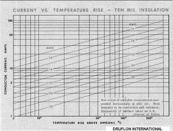
For Free Design Service, Contact: mukul@druflon.com; druflon@gmail.com; nkrishna@druflon.com TECHNICAL ADVISORY SERVICE on wire/cable design and related areas of electrical engineering is offered at no charge. Please let us know the statement of performance and test requirements, rather than material/size specs. Detailed information on Working Voltage (AC or DC), current, frequency,Zo,attenuation,longest inter-connection length,voltage drop, ambient conditions, (temperature and/or chemical environment), dimensional and weight limitations, unusual constraints or hazards,servicing problems etc. will help in optimum design. It is often observed that buyers specify wires or cables that are presently used in PVC or other lower temperature insulating materials, and require equivalent sizes -- not just of conductors but also overall diameters -- in PTFE. This kind of one-to-one substitution of lower temperature wires is not advisable for the simple reason of high cost. One should design the wire for each given application. For this purpose, as much of the details mentioned in the previous paragraph, as are available, need to be specified. With an experienced designer, it is often possible to substantially reduce the sizes of low-temperature wires for much the same performance at a marginal increase in cost, while providing the added bonus of much higher reliability in the long run. Any wire consists of materials with two completely opposite kind of properties: a highly conductive inside core which is the conductor, and a highly non-conductive material to cover the conductor that is the insulation. The insulation provides protection against voltage and higher voltages will need higher wall thickness of insulation, keeping in mind also the physical and mechanical requirements. On the other hand, the cross-section of conductor is determined based on the requirements of current (amperes). Based on the needs of flexibility, maximum working temperature, and other considerations, one is able to ascertain the material composition and construction as well as platings on conductor. For help in ascertaining the size of conductor for given current, we refer to a graph showing Current vs. Temperature Rise Above Ambient.
For example, if 5 amp current is passed through a 24 AWG conductor, the temperature rise above ambient will be about 24°C. If maximum ambient temperature is 50°C, then the maximum conductor temperature will be 74°C. For reasons of safety, it is advisable not to go beyond 130°C for Silver Plated Copper (SPC) and 180°C for Nickel Plated Copper (NPC) conductors. This is in the case of a single wire. For multi-cores, where a number of heat-emitting conductors are in close proximity of each other, further de-rating is needed and will depend on the actual conditions. Voltage dropis another important consideration, especially when working with low DC voltages, or when the inter-connection length is long, or there is heavy in-rush current during start up of heavy loads/motors. A thumb rule is that 3-5% of voltage drop can be acceptable under most situations, even though specific cases may need more stringent control. Questionnaire for High Voltage Corona Resistant (HVCR) Cable Design High Voltage Corona Resistant (HVCR) wires/ables need to perform under critical conditions. It is, therefore, necessary to carefully evaluate the application requirements, before a design is finalized. When specifying these wires, the designer needs to carefully differentiate between the actual maximum voltage that the wire is likely to be exposed to (working voltage or operating voltage, AC or DC), thetest voltage on 100% length (proof voltage) and Break Down Voltage (destructive tests on end-samples). In our case, it may also be worthwhile to consider the minimum Break Down Voltage required under the Progressive Stress Test. In order to offer an optimum design for HVCR wire/cable, as much of the information as available from the points listed below, will be helpful: 1. Details of HV cable presently used, construction (dia, material) For Free Design Service, Contact: mukul@druflon.com; druflon@gmail.com; nkrishna@druflon.com Teflon ® is a DuPont Trade Mark |