ADVANTAGES
APPLICATIONS
SPECIFICATIONS
SIZE TABLE
WHAT IS TWS?
ADVANTAGES OF TWS
ORDERING INFORMATION
WIRES PER U.S.A. MIL-W-16878
ADVANTAGES
APPLICATIONS
SPECIAL EQUIPMENT WIRES
QUALITY FEATURES
CAUTION
ADVANTAGES OF TWS
LIST OF MIL-W SPEC SHEETS
CONDUCTOR SIZE TABLE
INSULATED WIRE SIZES
COAXIAL CABLES PER MIL-C-17
TABLE OF COAXIAL CABLES
MULTI-CORE CABLES
HIGH VOLTAGE WIRES & CABLES
HVCR SELECTION GUIDELINES
HVCR QUALITY ASSURANCE
HVCR SIZE TABLE
HEATING WIRES
WIRES FOR FLOOR HEATING
TECHNICAL ADVISORY SERVICE
QUESTIONNAIRE FOR HVCR
PROPERTIES OF PTFE
COLOUR SCHEMES
APPROVALS
COMPANY PROFILE
CONTACT US
FEEDBACK
SITE MAP
OTHER RESOURCES
|
|
PTFE Insulated Hook-up/Equipment Wires as per
US
Navy's MIL-W-16878 (click here for
listing
of specification sheets) or British BS-2G-210 or Indian JSS
51034 are used for internal wiring of professional high-performance
electronic/electrical
equipment.
On this page, you will find:
1. Advantages of
PTFE insulation
2. Applications of PTFE
insulated Wires
& Cables
3. PTFE Insulated
Special
Equipment Wires
4. Special
Features --
Quality Assurance, Test Voltages
5. Caution
1. ADVANTAGES OF
PTFE
INSULATION
PHYSICAL/CHEMICAL
- Inert
to practically
all chemicals even at elevated temperatures
- Excellent
Resistance to Ultra-Violet radiation and stress-cracking
- Non-contaminating,
Non-toxic and bio-compatible
- Resistant
to fungus and mould growth
HIGH
TEMPERATURE
- Excellent
thermal
stability -- suitable for use from -200°C to
+260°C
- Fire (flame) proof
- Soldering iron resistant and suitable
for high density wiring
ELECTRICAL
- Suitable for very wide frequency range
(DC to above 10,000 MHz)
over wide temperature range
- Lowest dielectric constant (2.1)
- Lowest dissipation factor (below
0.0003)
- Highest volume and surface
resistivities (in Teraohms)
- Corona Resistance is fair (CR PTFE is
available for severe corona
conditions)
MECHANICAL
- Smaller size, lighter weight and much
higher reliability
- Cold-flow and cut-through resistance
-- fair (good mechanical strength)
- Excellent flex-life
2. APPLICATIONS
OF
PTFE INSULATED WIRES & CABLES
- Electronic
Test Equipment
- Communication
Equipment (mobile and manpack wireless sets)
- Equipment
for Aircraft, Radar, Navigation, Electro-mechanical applications,
Satellites,
Research Equipment for Aerospace, Navy & Meteorology
- Control
Equipment
for Atomic Energy, Satellite Launching, Ground Control, Reactors and
Process
Control, Telephone Exchange, Lifts
- Computers,
Flight simulators
- High
performance
motors, transformers and rectifiers
- Infra-red
sensing equipment
- Thermo-couple
and compensating cables
- Air-field
lighting equipment
- High
temperature
lighting fittings (sodium lamps etc.)
- Refrigeration
equipment
- Load
cells
and pressure transducers
- Electro-medical/Neuro-surgical
equipment
- High
temperature
control valves
- Furnace
and
oven wiring
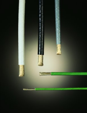
3. PTFE INSULATED
SPECIAL
EQUIPMENT WIRES
Please
refer
to table for commonly available sizes. Within the normal range,
larger
number of strands are available to improve flexibility and flex-life;
19 strands
up to AWG 30, 37 strands up to AWG 20 and 60 strands for AWG 9, 10, 11,
12
and 13. In the two larger sizes AWG 6 and 8, compact 61 strands
true
concentric constructions (compared to Rope lay 19 x 7) are about 15%
lower
in OD, weight and cost, although slightly stiffer.
We
offer
finer sizes, having thin-wall PTFE insulation, highly flexible (with
flex-life)
constructions using Silver Plated High Strength Copper Alloy
(SPHSCA).
Sizes as small as AWG 37/7/45 (0.43 mm). Even such fine sizes are
100%
tested.
For
Wire-Wrap
wire, advantages of PTFE insulation are now available in single strand
size
up to AWG 36 (OD 0.43 mm), and multi-strand 3607 or 3707 with OD 0.38
mm.
4. SPECIAL
FEATURES -- QUALITY ASSURANCE
- 100%
Physical
and Electrical testing (see below for test
voltages
)
- A
minimum
of 3 layers of PTFE tape, wrapped and sintered, provides balanced
bi-axially
oriented, concentrically placed insulation (for more details about
advantages
of TWS method, click here)
- Minimum
shrinkage/deformation
and no `run-away' problem at soldering-iron temperatures
- Surface
as
good as extruded wire without the disadvantages of extruded PTFE
insulation
in fine-gauge thin-wall types
- Certified
minimum BREAK DOWN VOLTAGE (on samples) to ensure higher, uniform and
predictable
performance
- Controlled
tigher tolerance on weight, PTFE density and conductor resistance
- Test voltages for
the three
common working voltages are:
|
Type |
Working Voltage
AC
RMS |
Dielectric Test
Voltage
for 1 minute |
Spark Test Voltage for for 1 second |
|
ET |
250 |
1500 |
2500 |
|
E |
600 |
2000 |
3400 |
|
EE |
1000 |
3000 |
5000 | 5. CAUTION
- Thin-wall
insulation
is not recommended for higher soldering iron temperatures and for
gauges larger
than AWG 20
- Stripping
of Tape-Wrapped-Sintered (TWS) PTFE insulation is generally difficult
on
automatic high-speed machines, more so, for thin-wall finer sizes
For Free Design Service, Contact:
mukul@druflon.com; druflon@gmail.com; nkrishna@druflon.com
Teflon ® is a DuPont Trade Mark
Copyright © 2002-2023 Druflon Electronics P. Ltd. & Druflon International. All rights reserved.
|
